
BCD has developed a variety of chips that can achieve negative voltage output, of which AP3012 and AP3031 are two commonly used. Both AP3012 and AP3031 are current-controlled PWM chips. These two chips integrate the switching transistor and feedback network inside the chip. The integration is high, which reduces peripheral components to a certain extent, saves system cost and saves space. . In addition, the AP3031 has a higher load capacity than the AP3012. The different load capacities of the two chips can meet different applications.
AP3012 Typical Application for Positive and Negative Voltage Output
The AP3012-based positive and negative voltage scheme is widely used in 4.3 to 10 inch LCD display systems. The application circuit diagram is shown in Figure 1.
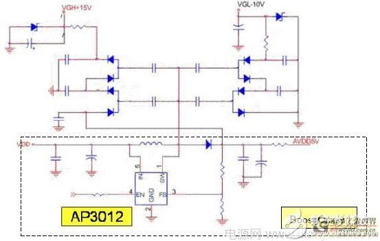
Figure 1. AP3012 shows a typical application scheme for positive and negative asymmetric output.
In this application, the AP3012 uses a boost circuit architecture that provides a stable 5V reference for 15V and -10V. The 15V and -10V are achieved by the conversion of several stages of charge pump circuits. This scheme can change the output voltage by adjusting the number of stages of the charge pump circuit. The structure is very simple and the use is quite flexible.
Due to the high integration of the AP3012 (integrated with switching tube and feedback network), the number of peripheral components of the system is reduced, and the practicality of the system is further improved. Therefore, the application of the AP3012 provides a lot of room for the cost and size control of the system.
Typical Application of AP3031 for Negative Voltage Output
As system applications continue to evolve, the supply current required by the system continues to increase. For example, in system applications such as data acquisition, a large number of operational amplifiers need to be provided with positive and negative bias voltages. In this way, a power chip with a larger load capacity is required to supply power thereto. Then the AP3031 is a good choice. Because the AP3031 has a strong load capacity, it is widely used.
Because the AP3031 is often used in systems with large operating currents. To reduce power loss, the AP3031 typically provides a single positive or negative bias voltage. Figure 2 shows an application circuit that uses the AP3031 to achieve a -5V output.
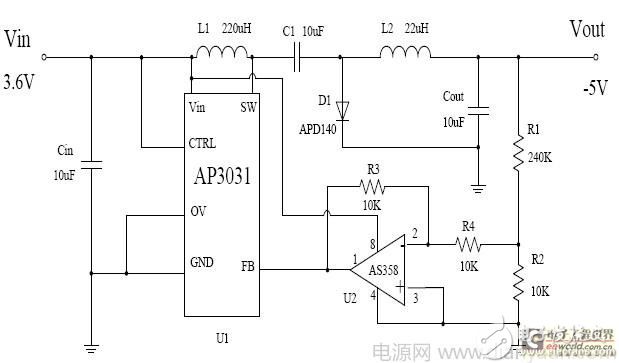
Figure 2. Typical application circuit for the AP3031 to achieve -5V output.
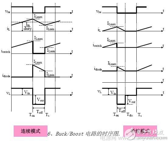
The AP3031 uses a Cuk circuit structure to achieve a negative voltage output. Figure 6 is a timing diagram of the Cuk circuit.
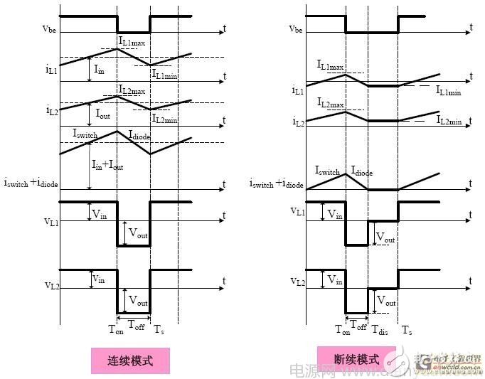
Figure 3. Timing diagram of the Cuk circuit.
This expression indicates that the input voltage of the Cuk circuit is not limited by the output voltage and can be greater than the output voltage or less than the output voltage. The range of input voltages can be made wide. Greatly improved the flexibility of circuit applications. The program's input voltage range is wide (3V ~ 16V), the output load capacity can reach 300mA.
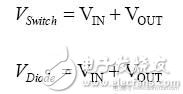
It is worth noting that the requirements are higher. Due to the structural reasons of the Cuk circuit, it is determined that the circuit has higher requirements on the withstand voltage of the device. See the following expression:
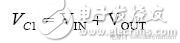
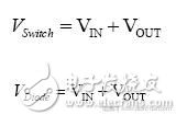
As can be seen from the above three expressions, unlike the Buck and Boost circuits, the voltage applied to the switch and the diode when the Cuk circuit is operating is the sum of the input voltage and the output voltage. Therefore, when selecting the switching tube and the diode, the input and output voltage should be taken into consideration at the same time.
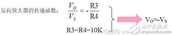
In terms of feedback, since the output is a negative voltage, an inverting amplifier is used, and the negative voltage signal of the sampled output is inverted and input to the feedback end of the chip.
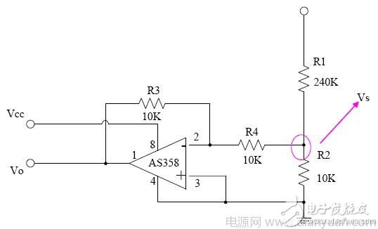
Figure 4. Structure diagram of the inverting amplifier.
Other typical applications for implementing a negative voltage output chip
If the system's input, the output voltage is low, and the input range is not wide, then BCD's AP3406A is also a good choice. The input range of the AP3406A is 2.5V~5.5V, and the maximum output current can reach 800mA. Since the AP3406A is a current-controlled PWM synchronous rectifier chip, it can achieve high efficiency. The AP3406A can implement a negative voltage output by building a Buck/Boost circuit structure. Figure 5 shows a typical application of the AP3406A to implement a negative voltage output.
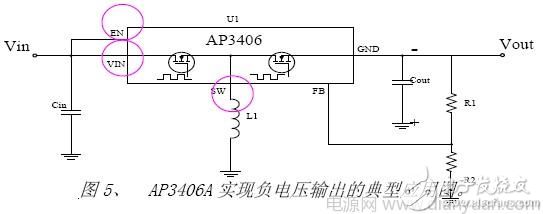
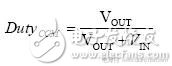
Duty cycle expression for Buck/Boost: 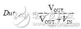
Compared with the AP3031 solution, this application scheme is simpler in structure and requires fewer devices (eliminating an inductor and an inverting amplifier), which further embodies the advantages of low cost of use and space saving of the system.
In addition, the circuit has the same voltage withstand voltage as the Cuk circuit.
The methods described above have been fully validated on the Demo board, the results are feasible, and have been accepted and adopted by customers, is a cost-effective solution to achieve a stable and reliable negative voltage.
KNB6-63 Miniature Circuit Breaker
KNB6-63 Mini Circuit breakers, also named as the air switch which have a short for arc extinguishing device. It is a switch role, and also is a automatic protection of low-voltage electrical distribution. Its role is equivalent to the combination of switch. Fuse. Thermal Relay and other electrical components. It mainly used for short circuit and overload protection. Generally, According to the poles, mini Circuit breaker can be divided into 1P , 1P+N , 2P, 3P and 4P.
KNB6-63 Miniature Circuit Breaker,Electronics Miniature Circuits Breaker,Automatic Miniature Circuit Breaker,Mini Circuit Breaker
Wenzhou Korlen Electric Appliances Co., Ltd. , https://www.zjmoldedcasecircuitbreaker.com