
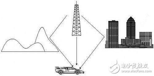
In the field of wireless communications, multipath refers to the propagation of radio signals from a transmitting antenna through multiple paths to a receiving antenna. The scattering of electric waves by the atmosphere, the reflection and refraction of the ionosphere by electric waves, and the reflection of electric waves by surface objects such as mountains and buildings all cause multipath propagation.
In a wireless transmission system, multipath refers to receiving two copies at the same time. These two copies have different transmission paths and have different transmission delays.
For example, a signal reflected from a building or other object is received by the receiver along with a directly transmitted signal (a non-reflective signal). This causes "stacking" in the television receiver - one can see that an echo with an attenuation in the horizontal direction is superimposed on the main image.
Another common example is the radio (especially the AM radio), which has a certain delay after being reflected by the ionosphere. This signal is received by the radio along with the directly transmitted signal.
In general, multipath has a detrimental effect on the system, but in MIMO systems, MIMO systems use different antennas to transmit copies of signals. Complex receiving systems combine different chips for processing to improve system performance.
Multipath impact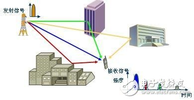
Multipath causes fading and phase shifting of the signal. Rayleigh fading is a statistical model of multipath channel with impulse response amplitude obeying Rayleigh distribution. For multipath channels with direct signals, the statistical model can be described by Rice fading.
The effect of multipath on communication quality can be visually seen in television signal transmission. The signal component arriving at the receiving antenna over a longer path is slightly later than the signal arriving at the antenna in a shorter path. Because the TV gun scan is from left to right, the late signal will superimpose a slightly right virtual image on the TV screen formed by the early signal.
For similar reasons, a single target will produce one or more virtual images on the radar receiver due to terrain reflections. These virtual images move in the same way as the actual objects they reflect, thus affecting the radar's recognition of the target. To overcome this problem, the radar receiver needs to compare the signal to a nearby topographic map and remove the signal from the reflection that appears to be below the ground or above a certain altitude.
In digital wireless communication systems, the inter-symbol-interference (ISI) generated by multipath effects affects the quality of signal transmission. Time domain equalization, orthogonal frequency division multiplexing (OFDM), and Rake receivers can all be used to combat interference caused by multipath.
The basic idea of ​​time domain equalization is to use the transverse filter to judge the next code sequence by using the currently received code sequence in the delay time, and remove the error code other than the judgment rule, thereby eliminating the error in the code and reducing the intersymbol interference. . For example, it is known that the next one of the coding sequence 11001 should be 10, if 01 is present, it is removed, and then the next sequence is judged until the correct coding sequence is restored.
Orthogonal Frequency Division Multiplexing (OFDM) technology is one of the key technologies adopted by LTE (Long Term Evolution (UMTS) technology). Its basic idea is to decompose the data stream into several independent low-speed bit streams, speaking from the frequency domain. It is divided into multiple subcarriers and then sent out in parallel. This can effectively reduce inter-symbol interference due to multipath transmission during high-speed transmission. In order to minimize the multipath effect and inter-symbol interference caused by other factors, the OFDM technology also sets an idle transmission period in each signal, which is called a guard interval, which is greater than the maximum delay of the channel, so that Inter-code interference caused by delays on the next signal. As shown in the figure, the dotted line shows the idle segment without signal. At this time, although the overlap of the signals before and after the multipath transmission occurs, since there is no signal in the idle segment, the overlapping portion does not cause interference. In practical applications, since there is no waveform in the idle transmission period, if it is an overlapping part of multiple carriers, the orthogonality is destroyed, and inter-channel interference (ICI, Inter Channel Interference) is caused due to multipath transmission, and is idle in this case. The time period is also filled with a signal, called a cyclic prefix, which is discarded when receiving. The dotted line in the figure is added to the signal waveform and becomes the cyclic prefix.
Multipath effects are not only a frequent cause of fading, but also one of the fundamental factors limiting transmission bandwidth or transmission rate. In short-wave communication, in order to ensure that the maximum delay and minimum delay difference of the circuit in multipath transmission are not greater than a certain value, the operating frequency requirement is not lower than a certain percentage of the highest available frequency of the circuit. This percentage, called the multipath reduction factor, is one of the important criteria for determining the lowest available frequency of a circuit. The figure shows the relationship between the multipath reduction factor and the path length. Anti-multipath measures in tropospheric propagation channels typically have suppression of ground reflections, narrow antenna beams, and diversity reception.
Measures to solve multipath interferenceAnti-multipath interference mainly has the following aspects:
(1) Improve the distance measurement accuracy of the receiver, such as narrow correlation code tracking loop, phase ranging, smooth pseudorange, etc.;
(2) anti-multipath antennas;
The smart antenna uses a combination of multiple antenna elements for signal processing, automatically adjusting the transmit and receive patterns to achieve optimal performance for different signal environments. Smart antenna is a kind of spatial division multiple access (SDMA) technology, which mainly includes two aspects: spatial filtering and direction of arrival (DOA) estimation. The main idea of ​​spatial filtering (also called beamforming) is to use the spatial distribution of signals, interference and noise, and use linear filtering techniques to suppress interference and noise as much as possible to obtain the best possible signal estimation.
The smart antenna controls the weighting by an adaptive algorithm, and automatically adjusts the antenna's pattern so that it forms a null in the interference direction, cancels the interference signal, and forms the main beam in the direction of the useful signal to achieve the purpose of suppressing interference. The automatic adjustment of the weighting coefficients is the beamforming process. Smart antenna beamforming greatly reduces multi-user interference while also reducing inter-cell interference.
(3) Anti-multipath signal processing and adaptive cancellation techniques.
Multiple access interference is a result of the traditional single-user reception scheme used in multi-user systems. The single-user receiver uses the matched filter as a tool for correlation decision, and does not consider the existence of multiple access interference. Each user's detection does not consider the influence of other users, and is a strategy for single-user detection. In general, there is no multiple access interference when a single user transmits, but in a multi-user environment, when the number of interfering users increases or their transmit power increases, multiple access interference cannot be ignored. Therefore, multi-user detection technology is adopted, and its algorithm has an optimal detection algorithm and a sub-optimal detection algorithm.
In the CDMA system, the multi-user detection problem is actually the process of extracting the target random variable from the observations of linearly combining several random variables and adding noise. In general, multi-user receivers not only need to know the spread spectrum information of all users but also need to be constantly updated as the system changes. In addition, it is necessary to estimate the user's amplitude, phase, and timing information for the detection of the receiving end, which will inevitably lead to an increase in computational complexity. Due to this limitation, multi-user detection is mostly applied to the base station side. To apply it to the mobile station side, one implementation method is to transmit a known training sequence to adaptively adjust the receiver parameters to an ideal working state. . This method has obvious drawbacks: when the channel response is abrupt or the number of users changes, the training sequence must be resent, and frequent transmission of the training sequence will result in great waste of spectrum resources. In view of the above reasons, the development of blind multi-user detection algorithms that do not require all users and the need to send training sequences has become a new hot spot in the industry. Taking linear detection as an example, linear blind multiuser detection is a process of finding a weight vector without knowing the interference of the user's spread spectrum information and the training sequence. Since all users work independently in the same modulation mode, it can be assumed that the information symbols of each user and the different symbols of the same user are independently and identically distributed, and the difference in amplitude can be reflected in the coefficients of the channel response mixing matrix.