
1 Introduction
With the rapid development of bus technology and communication technology, various measuring instruments are equipped with intelligent communication functions, and the communication between the controller and the intelligent instrument has gradually become an indispensable part of the project.
The current popular field buses are mainly Modbus, Profibus, CAN, LonWorks and so on. Due to the differences in the interface technology and communication protocol of each bus, the transmission media are also different. For example, the common Modbus interface uses RS 485, so the data is transmitted through polarized twisted pairs. In the late 1980s, Echelon (Echelon) of the United States began to develop the LonWorks technology platform, believing that he will become a common standard for control networks.
2 LonWorks bus introduction
The LonWorks control network is similar in some ways to a data network called a local area network or LAN. The data network consists of computers connected by routers that combine various communication media, and they use a common protocol to communicate with each other. The control network contains similar components optimized for cost, scale, performance and response characteristics.
The private network that realizes the ideal control function is called the local operation network 1ΩN (Local OperaTIng Network). His features enable the network system to be extended to a class of applications where data networking technology is powerless. Control system and device manufacturers can shorten the development and design time by combining the design of LonWorks in their products. The complexity of the LonWorks control network is different. A small network can be built from a few nodes to a building control system with thousands of nodes.
The LonTalk communication protocol is the core of LonWorks technology. The protocol provides a set of communication services, so that the applications in the device can receive or send data to other devices in the network without knowing the network topology, name, address, or functions of other devices [1]. The protocol can selectively provide end-to-end message confirmation, message confirmation and priority confirmation. It is a layered, packet-based peer-to-peer communication protocol that uses a "CSMA" algorithm similar to that used by Ethernet To deal with online message conflicts.
Each node in the LonTalk control network is assigned its own logical address, which consists of two parts. The first part is the domain ID of the specified domain, and the second part is the node address. The communication between nodes and nodes must first know the logical address, and then through the bound network variables to achieve. Network variables (NV) are any data items (temperature, pressure, or valve opening, etc.), they are a device-specific application that is expected to be obtained from other devices on the Internet (input NV) or provided to other devices (output NV). The application in the device does not need to know where the input NV comes from or where the output NV goes, because there will be a process of variable "bundling" during network design and installation, so that the input NV of one device and the output of another device A logical connection is established between NVs, which can be understood as the establishment of a "virtual circuit". The logical address and network variables provided by each node are fixed in the neuron chip.
The LonTalk protocol is independent of medium in design, which enables the LonWorks system to communicate on any physical transmission medium. Commonly used channel types are TP / XF-1250, TP / XF-78, TP / FL-10, PL-2X (power line), etc., and the maximum transmission rate can reach 1.25 Mb / s.
3 Brief introduction of STEC2000 controller
STEC2000 controller is an embedded controller independently developed by Beijing Shuorenshidai Technology Co., Ltd. It is based on embedded technology and adopts Motorola 32-bit high-speed CPU and embedded real-time Linux operating system. It integrates on-site collection, display operation, control and communication, and can be widely used in municipal (heating, tap water, gas, etc.), building automation (air conditioning, security, etc.) and other fields. The STEC2000 controller adopts a modular architecture, which can flexibly assemble a few points to hundreds of points of field control equipment according to requirements.
The CPU main control module adopts a 32-bit CPU with a frequency of 66 MHz, which is embedded with the real-time Linux operating system independently cut by the company, and has an 8 MB FLASH chip and a 16 MB electronic disk with 8 on the backboard Expansion slot. Different I / O modules can be configured as required; the analog input (AI) module has 8 analog input channels, each channel uses a differential input circuit, which can effectively suppress common mode interference, and can accept a current of 4-20 mA, A variety of commonly used analog input signals such as voltage 0 ~ l0 V; analog output (AO) module has 4 analog output channels, you can select the output current or voltage signal through the jumper to control various devices on the spot; digital input The human (DI) module has 12 digital input channels, accepting the on-site dry node switch status, of which the first 3 channels can be used as pulse counters; the digital output (DO) module has 8 relay output channels with a relay capacity of 130 V AC / l A, 125 V DC / 1 A; LCD and keyboard operation module with 5-inch 256-color LCD display and membrane keyboard for on-site human-computer interaction.
3.1 Measurement function
The STEC2000 controller collects temperature, pressure, heat and other primary instrument parameters and performs bad number filtering. The controller supports the conversion of the collected current and voltage data into corresponding physical quantities in a user-defined manner. The data scan period can be set between 0.05 and 2 s.
3.2 Storage function
The physical quantity data is saved once every 1 minute (configurable setting), and will not be lost after power off. Has a storage space of not less than 8 MB.
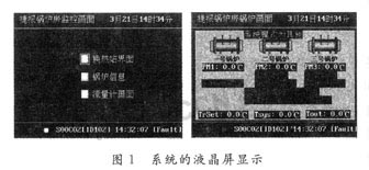
3.3 Display function
The STEC2000 controller supports a 5-inch color LCD screen. Users can freely configure the display screen and parameters.
3.4 Communication function
STEC2000 controller has built-in hardware facilities such as Socket Server, standard serial port (9-pin), RJ45 Ethernet interface, RJ11 telephone interface. The controller supports TCP / IP, Modbus, PPP and other protocols, Soket connection, 232/484 communication, Ethernet communication, telephone dial-up communication and wireless communication connection (GSM, GPRS, etc.).
3.5 Self-checking function
After the STEC2000 controller is powered on, it automatically checks whether the main board, peripheral equipment and I / O equipment are normal, and gives an alarm if there is any abnormality.
3.6 Control function
STEC2000 controller supports PID control, logic control, fuzzy control and other control methods, which can be selected through simple configuration. The controller also supports users to conduct secondary development in a scripting language. Control scan period is less than 200 ms (scan period can be defined).
3.7 Fault alarm
When an alarm event occurs, the STEC2000 controller will send an alarm to the host computer through the corresponding communication method until receiving the confirmation information from the host computer. The alarm content includes: the time when the fault occurred, the fault content, and the fault parameter value (or status). At the same time, the fault information will be displayed in the alarm information column of the LCD. When multiple alarms exist, the alarm information will be scrolled.
3.8 Human-computer interaction
The user can perform human-computer interaction through the keyboard of the STEC2000 controller: select the control method, set the parameter value, and cancel the alarm.
3.9 Web access
The STEC2000 controller has a built-in Web Server to publish the webpage of the controller's operating status. Users can log in and browse the webpage from any place via telephone line or Ethernet to understand the controller's operation. This function is protected by user password.
3.10 Remote configuration
STEC2000 controller supports remote configuration update and program control. For example, the user can establish a connection with the controller via telephone, Ethernet, etc., and then configure the controller as if it were local. This function is protected by user password.
3.11 Flexible configuration
One CPU main control module can support up to 8 expansion modules, and the user can freely configure the I / O module according to the type of data to be collected.
3.12 Perfect configuration function
The STEC2000 controller provides a visual graphical configuration environment running under the Windows operating platform to support the configuration of various functions such as data, control programs, display operations, alarms, communication management, and data storage.
4 Gas boiler monitoring
Ningxia Hanas Natural Gas Thermal Power Co., Ltd. built 60 natural gas boiler rooms in Yinchuan City. In order to achieve unattended operation, it is necessary to establish a local control room in each boiler room and a central main control room. A local control room for centralized monitoring.
In order to achieve centralized monitoring, in addition to the on-site temperature and pressure and the control of each water pump, it is necessary to communicate with the gas flow meter and the boiler controller. The gas flowmeter adopts Zhejiang Tianxin instrument, the specific communication protocol is contacted with the manufacturer, and will not be repeated here. The boiler is a German Fissman boiler, the boiler controller is Victronic 333, and the LonWorks communication bus is used. STEC2000 does not have that neuron chip, so to find a way to convert the bus interface, the implementation method is introduced as follows:
Modbus is a general language applied to electronic controllers. Through this protocol, controllers can communicate with each other via a network (such as Ethernet) and other devices. He has become a general industry standard [2], so a gateway can be used to realize the conversion between LonWorks bus and Modbus bus. The neuron chip is embedded in the gateway, and special software can be used to bind the boiler controller to the gateway variable. For example, the outdoor temperature can be bound to the 25th and 26th bytes in the gateway, and the system water supply temperature is bound to the first 7, 8 bytes, etc., another interface of the gateway is RS 485 interface, which can realize communication with STEC2000. The specific code is as follows:
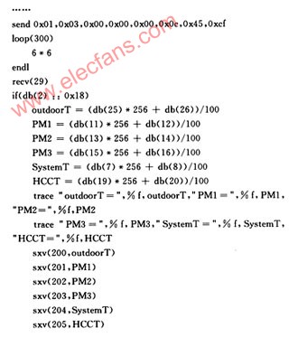
The standard Modbus protocol uses an RS 232C compatible serial interface. He defines the pins, cables, signal bits, transmission baud rate, parity, etc. of the connection port [2]. In actual projects, due to the distance factor, most of them use the RS 485 interface with a transmission distance of 1 200 m. The controller communication adopts the master-slave technology, that is, the master controller "question", the slave controller "answer", as in the above code send Ox01 ... is to require the slave controller to return the actual value of all physical quantities on site, the master control Recv (29) means to accept 29 bytes. The next step is to decode the 29 bytes according to the communication protocol provided by the manufacturer, and assign the obtained values ​​to the variables one by one to display them.
 |
After the control data of the boiler is collected to the STEC2000 controller, it is sent to the upper computer software of the monitoring center via broadband to realize remote monitoring of the boiler.
5 Conclusion
The STEC2000 controller supports multiple communication methods and can be applied in different environments to achieve communication with multiple buses. The development of communication scripts is simple and has been recognized by the technical personnel of the user. With the stable communication with the LonWorks bus, coupled with the original heating network monitoring experience, the requirements of the user have been perfectly achieved.
Heavy Duty Connector, also known as HDC, is widely used in construction machinery, textile machinery, packaging and printing machinery, tobacco machinery, robots, rail transit, heat runner, electric power, automation and other equipment requiring electrical and signal connection. The international advanced features of Heavy Duty Connectors in structural design and material usage make the connectors outstanding in electrical performance.The reliability of the electrical connection system can not be achieved by the traditional connection method.
Heavy Duty Connector Inserts are mainly used for electrical and signal connection between different equipments and function units , its rich combination bring more convenience and effectively simplify wiring connection even in the complex wiring environment.
Heavy Duty Connector Inserts
Ip68 Cable Connector,24 Pin Heavy Duty Connector,Heavy Duty Connector Inserts,Duty Heavy Electrical Cable Connectors
Suzhou WeBest Electronics Technology Co.Ltd , https://www.webestet.com